 3D LabMovie.BYU models with camera, clipping, culling and Phong lighting in the browser
A lab assignment from 1998
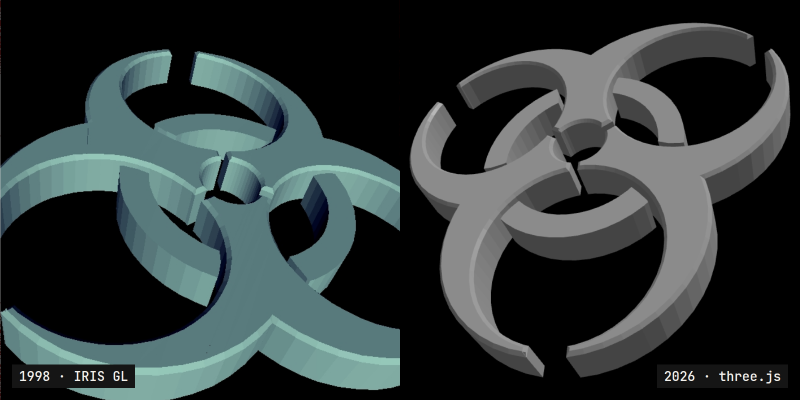
In the spring of 1998 I took the course Computer Graphics and Visualisation C, 5 credits, at Umeå University. Lab 2 was to write a program that loads 3D models and draws them on screen – with its own camera, its own projection, its own clipping, its own visibility test and its own lighting. It was written in C with IRIS GL on an SGI machine, and the graphics library was only allowed to draw the finished result: lines and filled polygons in screen coordinates. We computed everything else ourselves.
The program, gfx.c, is dated 2 February 1998. The screenshots are from 5 February. The models came with the course, in a format called Movie.BYU.
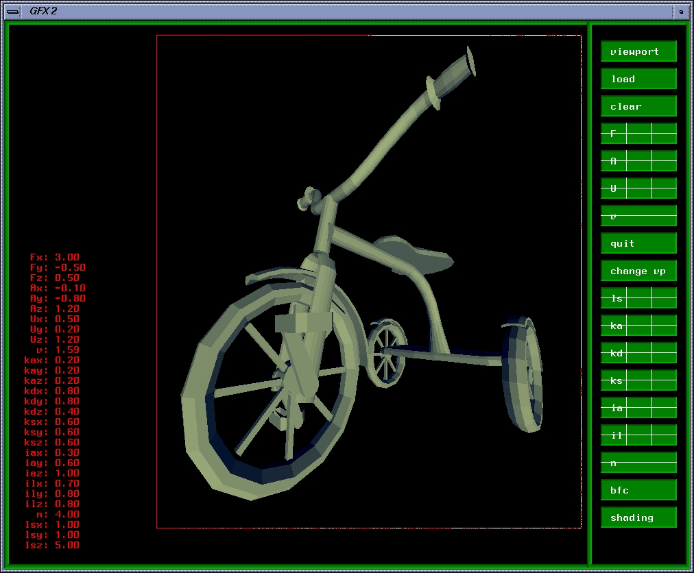
Today the same lab lives on as 3D Lab on Burn Tokens Repeat, translated to JavaScript and three.js by Claude Code. This post walks through what the lab actually does, step by step: the format, the camera, the projection, the clipping, which faces are visible and how the light is computed – with the maths and a worked example using today's default values. Claude Code drew the diagrams as SVG.
Movie.BYU – a nearly extinct format
Movie.BYU was a graphics system from Brigham Young University in Utah, written by Henry N. Christiansen, a professor of civil engineering, and Michael B. Stephenson. The manual, A General Purpose Computer Graphics Display System, is from September 1976, and in 1979 the system was described in a paper in an ASCE journal. It could show both line drawings and shaded colour images, and was used mostly for looking at finite element models – in 1984 NASA Langley wrote about how they had extended it for animation, and Cray Research advertised it in 1985.
The program is no longer maintained, but the geometry format lives on. VTK has a reader and a writer for it, and Ansys EnSight can still read it. The format is described by Paul Bourke and John Burkardt.
A file has four parts: a header with the number of parts, vertices, polygons and edges; a range for each part; the x, y and z of every vertex; and finally the polygons as lists of vertex indices. Indices start at 1, and the last vertex of each polygon is written with a minus sign – so no separate vertex count per polygon is needed. The fields come from FORTRAN, with fixed widths (10I8 for integers, 6E12.5 for floats), but most readers just split on whitespace.
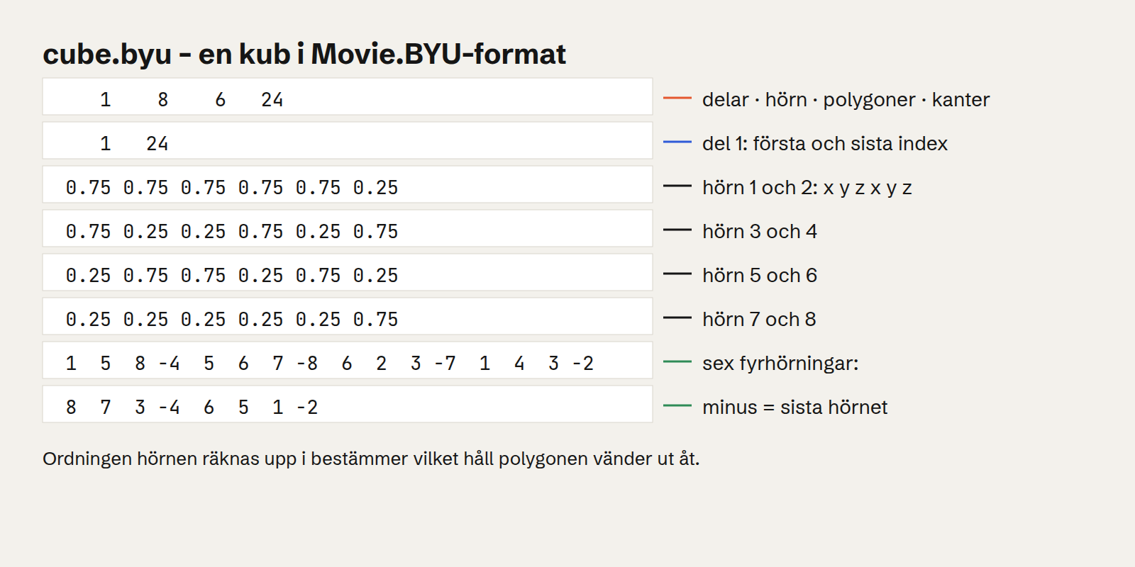
The order in which the vertices are listed matters: seen from outside they go counter-clockwise. It is the only way the file says which side is the outside, and both the visibility test and the lighting depend on it.
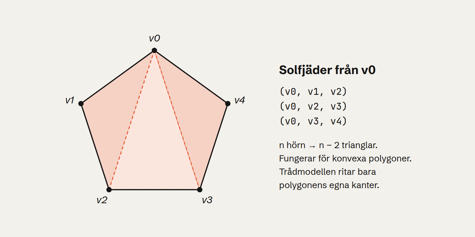
WebGL draws surfaces only as triangles, so today's version splits each polygon into a fan from the first vertex. That works for convex polygons, which is what the lab's models have. The wireframe still draws the polygons' own edges, so the diagonals don't show.
From file to pixel
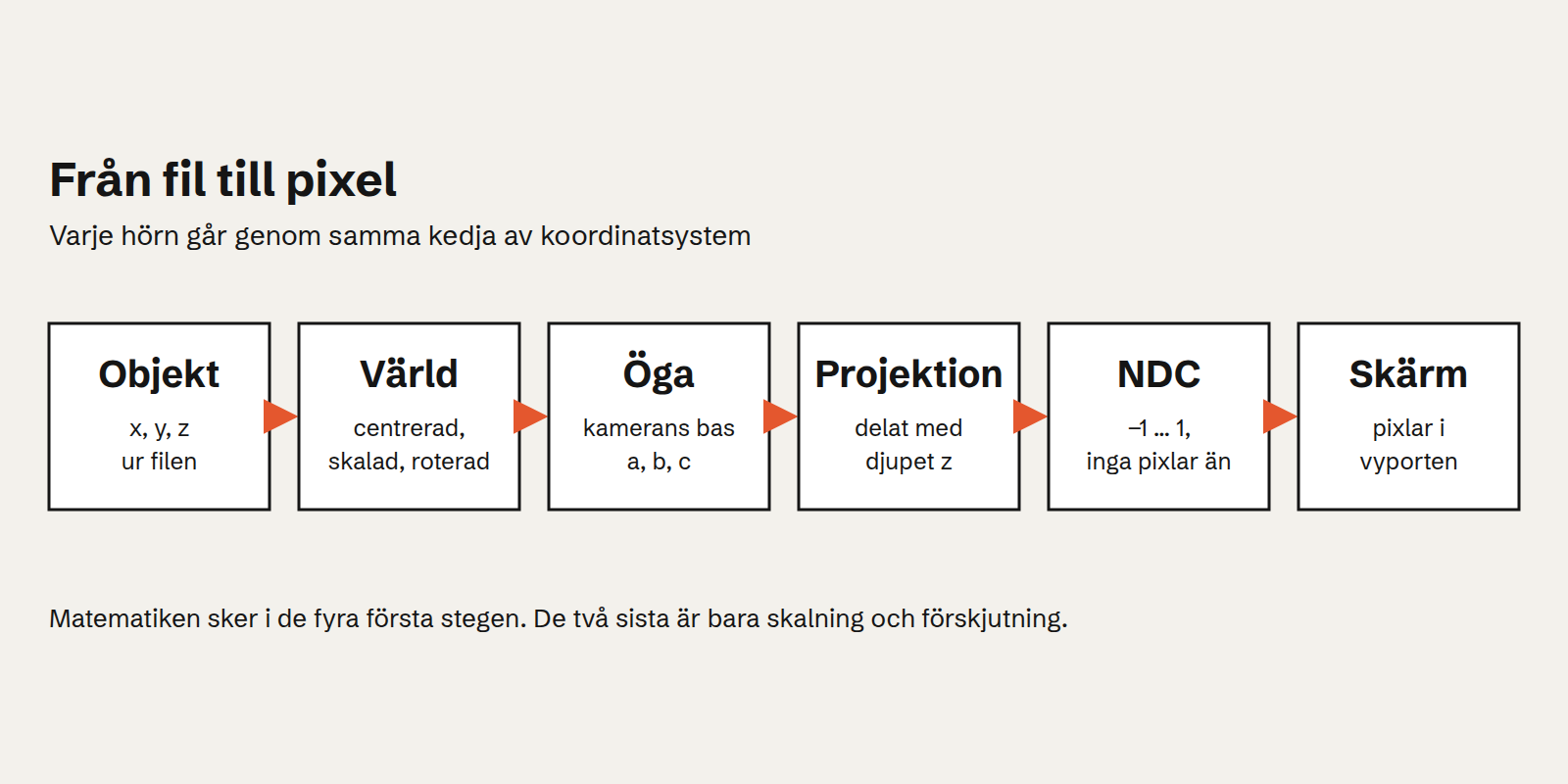
Every vertex goes through the same chain of coordinate systems. The model's own coordinates are placed in the world, the world is expressed in the camera's coordinates ("eye"), the projection divides by depth, and the result is scaled to normalised coordinates (NDC) and then to pixels in a window. The original had up to four such windows – viewports – on screen at once, each with its own camera and its own light.
The camera: F, A and U
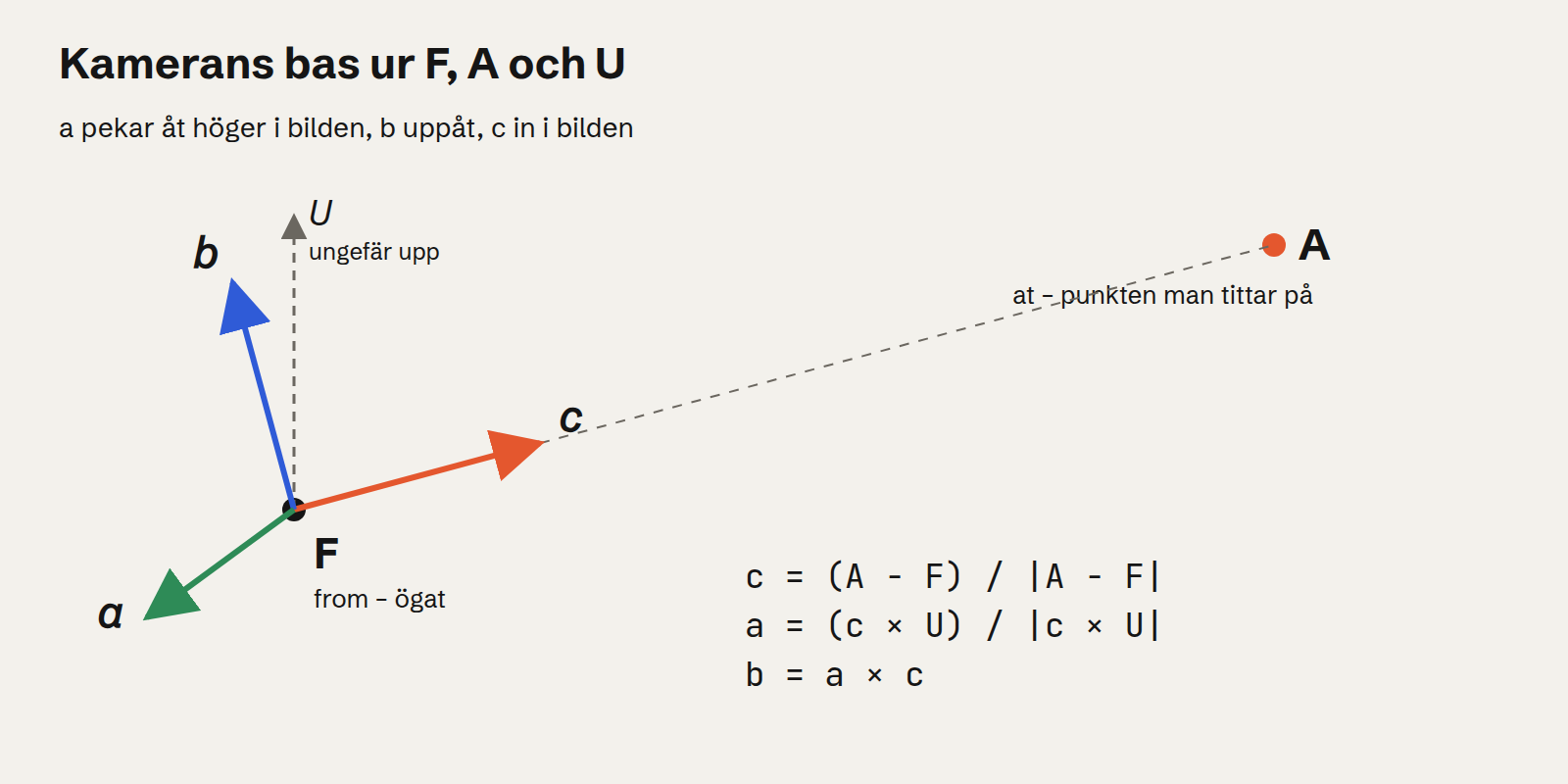
The camera is described by three vectors: F (from), where the eye is, A (at), the point you look at, and U (up), roughly which way is up. From them an orthonormal basis is built – three vectors of length one, perpendicular to each other:
c = (A − F) / |A − F|          viewing direction
a = (c × U) / |c × U|          sideways
b = a × c                      up in the image
U doesn't have to be perpendicular to the viewing direction. The cross product removes what's wrong: a becomes perpendicular to both c and U, and b perpendicular to the other two. It only fails if U points straight along c, because c × U is then the zero vector.
Changing to eye coordinates is then three dot products per vertex – the projection of P − F onto each of the axes:
xe = (P − F) · a
ye = (P − F) · b
ze = (P − F) · c
After that the eye is at the origin looking along the z axis. Everything that follows is simpler for it.
Perspective
A point twice as far away should look half as big. Put an image plane at distance d in front of the eye and draw a line from the eye to the point. Where the line crosses the plane follows from similar triangles:
y′ / d = ye / ze    →    y′ = d · ye / ze
x′ = d · xe / ze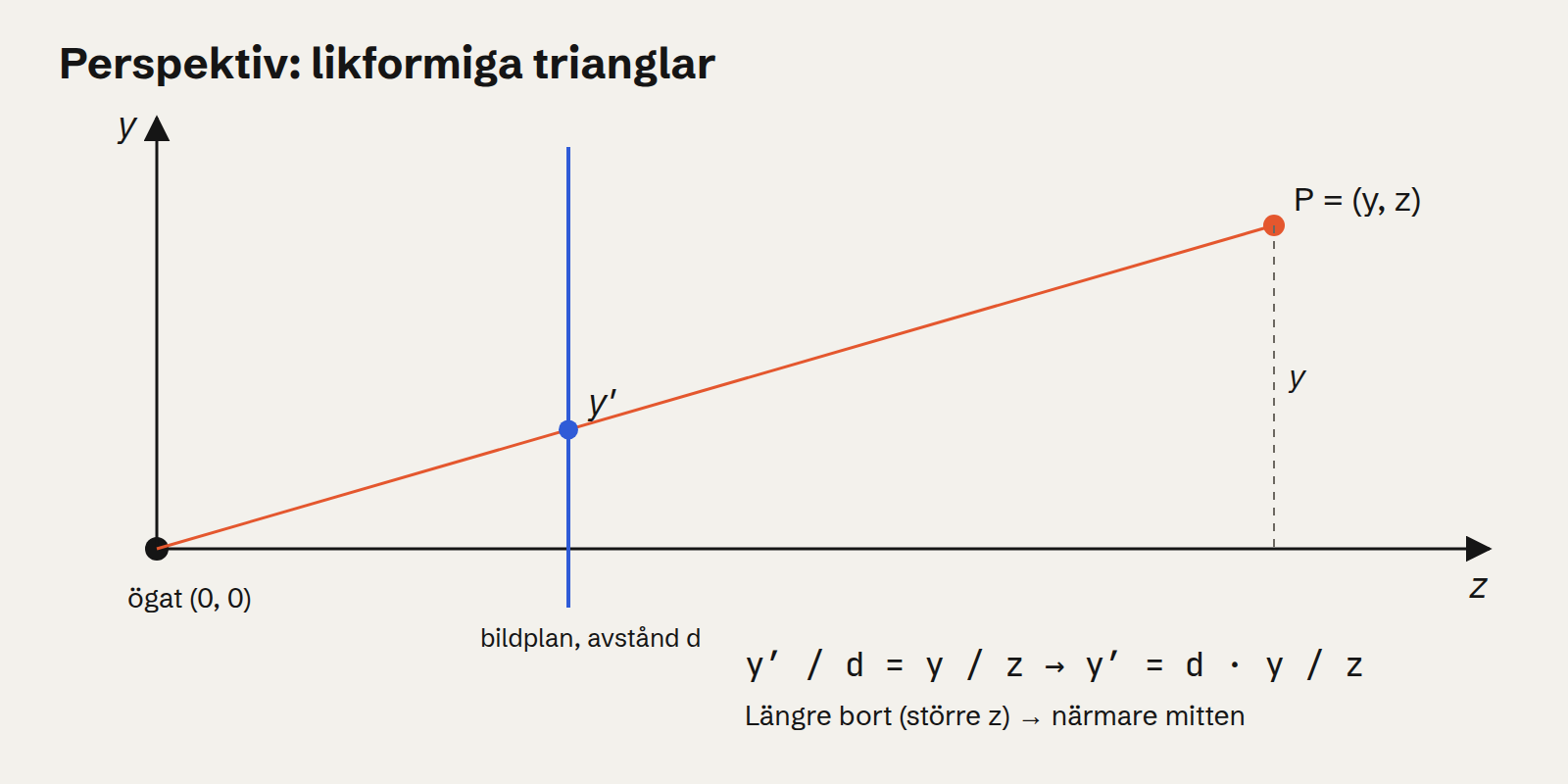
The original scales the result straight to the viewport. With the view angle v, the viewport's centre (Xvc, Yvc) and its width and height (Vw, Vh):
T  = 2 · tan(v / 2)
Xs = Xvc + (xe / ze) · Vw / T
Ys = Yvc + (ye / ze) · Vh / T
You can check it with a point exactly at the edge of the field of view. There xe / ze = tan(v / 2), and then Xs = Xvc + Vw / 2 – exactly the viewport's right edge. With v = 45°, T = 2 · tan 22.5° ≈ 0.828. A point with xe / ze = 0.25 lands 0.25 / 0.828 ≈ 0.30 viewport widths right of the centre.
Today's version has the same default view angle, 45°. The difference is that three.js does the same thing with a 4×4 matrix and a division by w, and also keeps the depth for the z-buffer.
Clipping: Cohen–Sutherland
A line that goes outside the window has to be shortened before it is drawn. Cohen–Sutherland gives each end point a four-bit code, one bit per edge: 8 if the point is above, 4 below, 2 to the right and 1 to the left. Points inside the window get 0000.
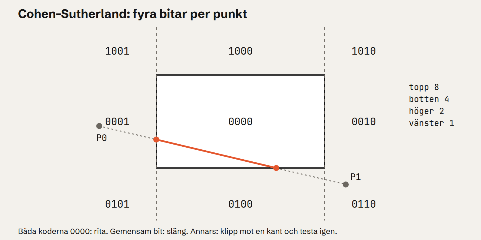
Then the codes decide almost everything:
- Both codes 0000: the line is entirely inside. Draw it.
- The codes share a bit (
c0 & c1 ≠ 0): both points are on the same outside. Discard the line. - Otherwise: take a point that is outside, move it to the intersection with one of the edges it is outside of, recompute its code and start again.
The intersection comes from the line's equation. Against the left edge x = xmin and the top edge y = ymax:
y = y0 + (y1 − y0) · (xmin − x0) / (x1 − x0)
x = x0 + (x1 − x0) · (ymax − y0) / (y1 − y0)
Each round removes at least one bit, so it takes at most four rounds. In the original the wireframe's edges are clipped this way. The filled polygons were left to IRIS GL. Today the GPU does the clipping, against all six sides of the view volume.
Which faces are visible?
The normal
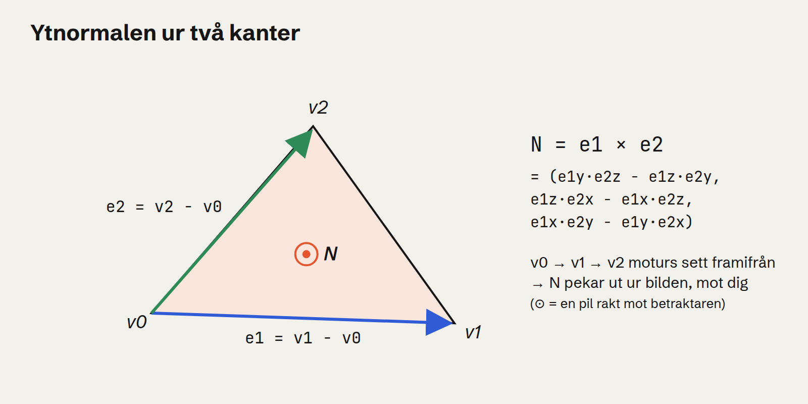
The normal is a vector perpendicular to the surface. It is given by the cross product of two edges leaving the same vertex:
e1 = v1 − v0
e2 = v2 − v0
N  = e1 × e2
   = (e1y·e2z − e1z·e2y,
      e1z·e2x − e1x·e2z,
      e1x·e2y − e1y·e2x)
Since the vertices go counter-clockwise seen from outside, N points outwards. The original computed (v1 − v2) × (v3 − v2), the same thing with the middle vertex as the starting point. If the first three vertices lie on a line, N is the zero vector, and then it tried vertices 2, 3 and 4 instead.
Backface culling
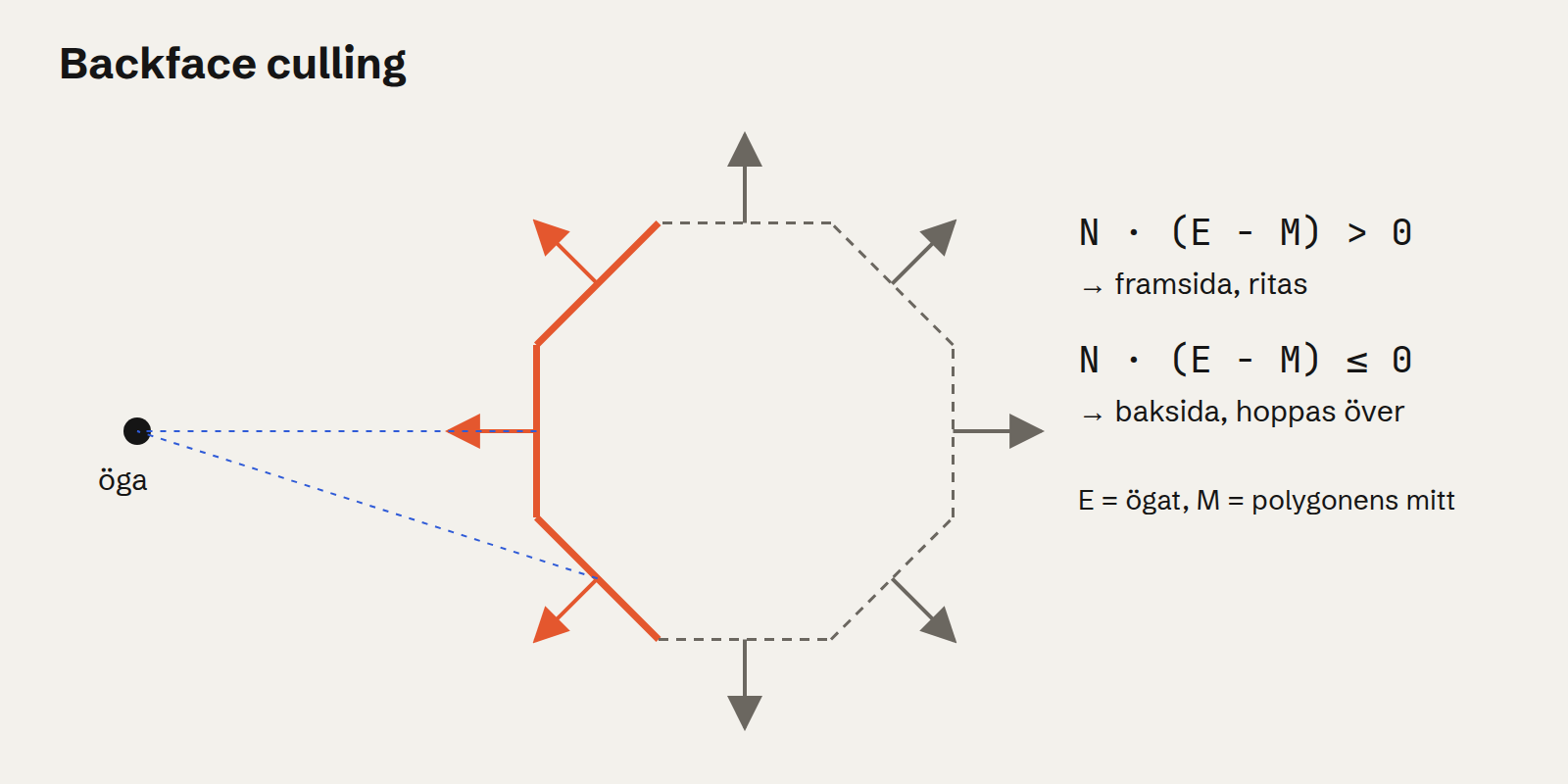
In a closed object roughly half of the faces point away from the eye. They can be skipped. The test is a dot product between the normal and the vector from the polygon's centre M to the eye E:
N · (E − M) > 0    →    front face, draw
N · (E − M) ≤ 0    →    back face, skip
In eye coordinates the eye is at the origin, so the original computed N · (0 − M), with M as the average of the first three or four vertices. Today's wireframe does the same test in world coordinates, with the camera's position as E.
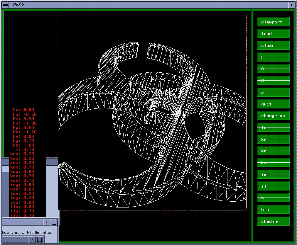
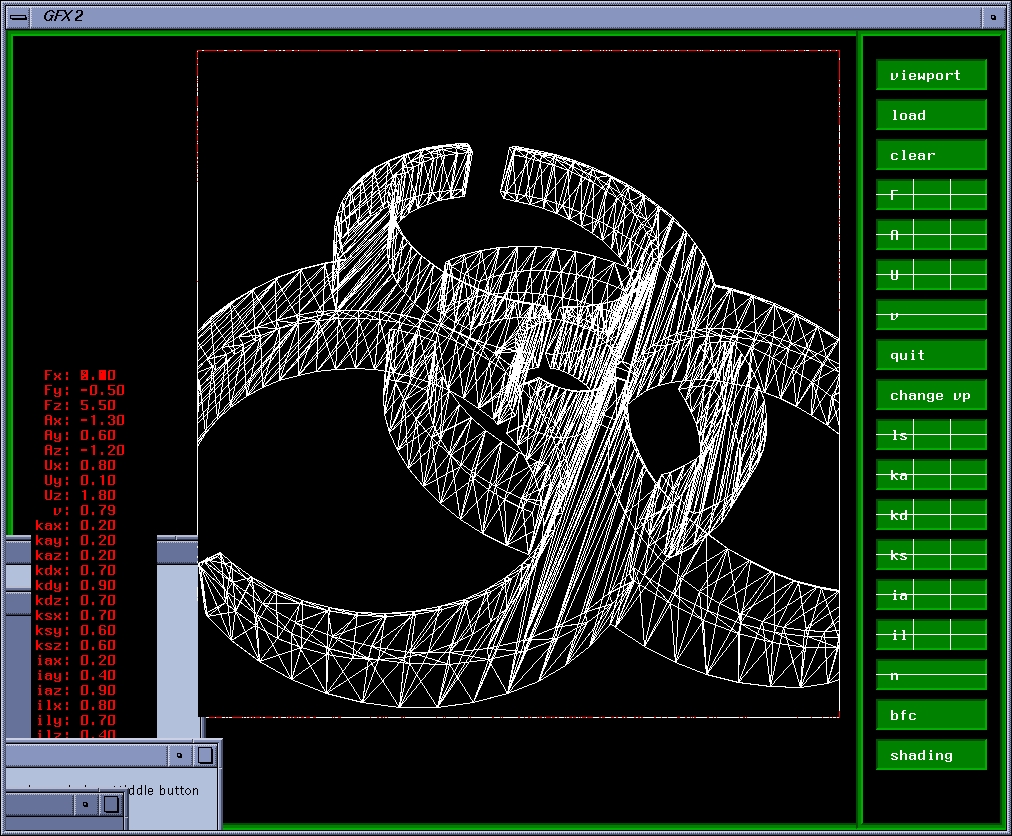
This is what it looked like in 1998, with and without culling:
And today:
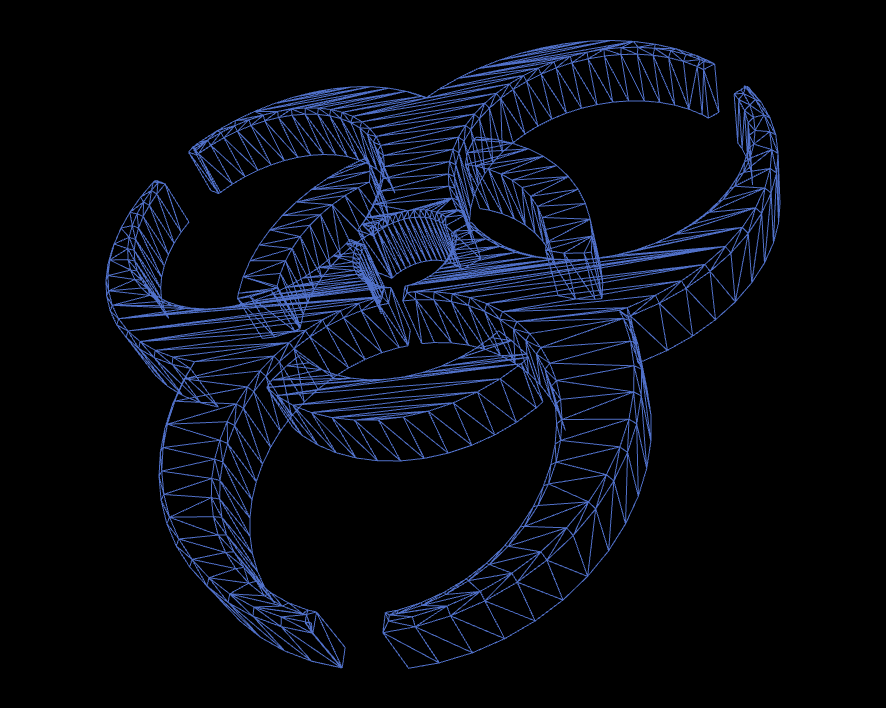
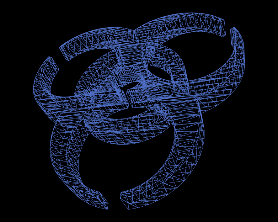
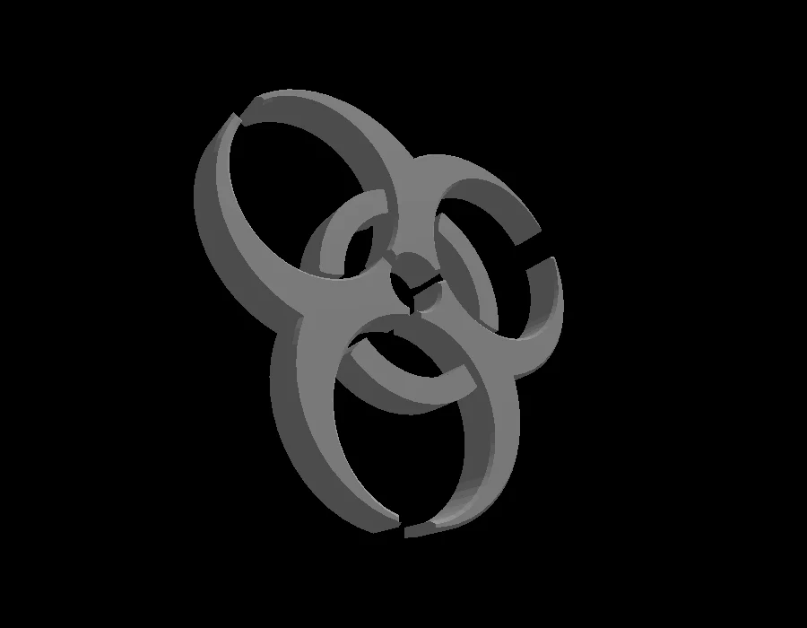
Culling is only enough for a single convex object. In the hazard model front faces hide other front faces, and then the order has to be right as well.
The painter's algorithm and the z-buffer
The original sorted the polygons by the greatest depth among their vertices and drew them back to front, like a painter who paints the foreground last. It is simple and works most of the time. But two polygons that intersect, or three that overlap in a ring, have no order that is right.
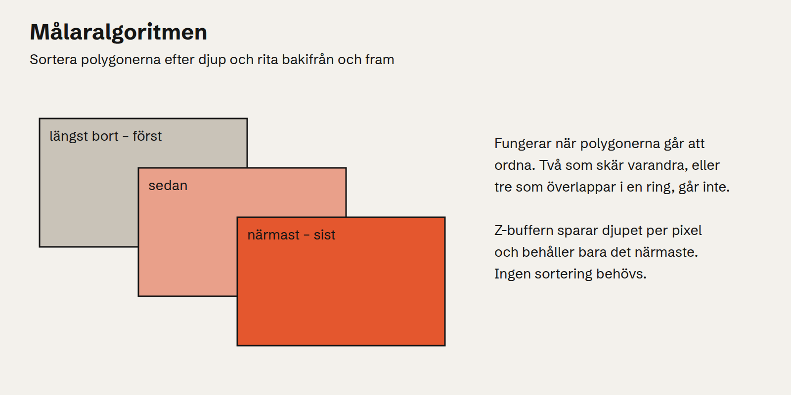
Today's version uses the z-buffer instead: for every pixel the depth of what has already been drawn is stored, and a new pixel is only drawn if it is closer. No sorting is needed, and intersecting polygons come out right.
The light: Phong's model
In 1975 Bui Tuong Phong described a lighting model that is still the basis of real-time graphics. It splits the light into three parts: an ambient light that lights everything equally, a diffuse light that depends on how the surface faces the light source, and a highlight that depends on where the viewer is.
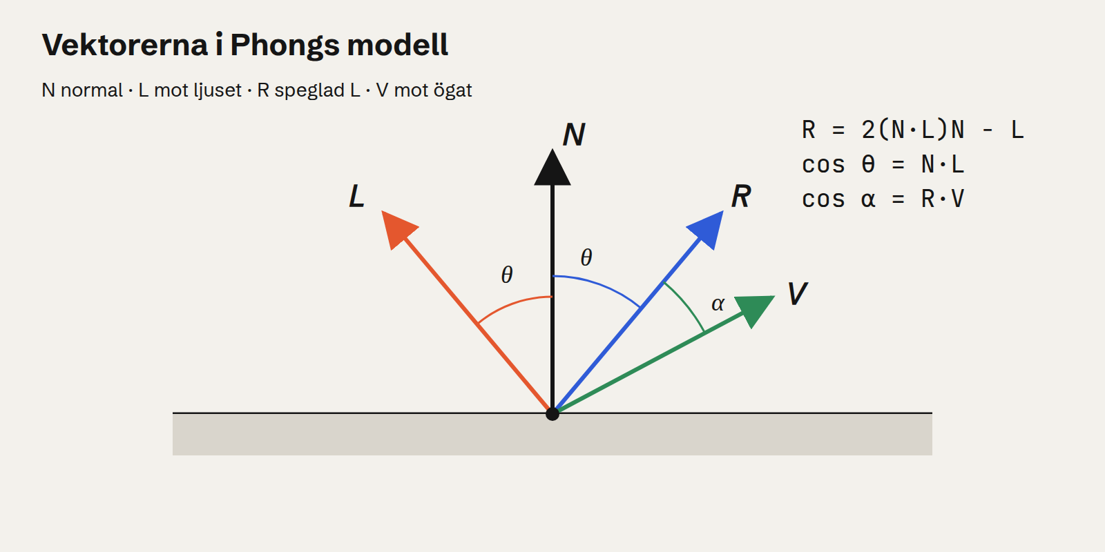
With all vectors normalised to length one:
cos θ = N · L            angle: normal to light
R     = 2 (N · L) N − L  the light mirrored in the normal
cos α = R · V            angle: reflection to eye
The reflection can be derived. Split L into a part along the normal, (N · L) N, and a part along the surface, L − (N · L) N. Mirroring keeps the part along the normal and flips the part along the surface: R = (N · L) N − (L − (N · L) N) = 2 (N · L) N − L.
In the original the light per colour channel was:
I = Ia·Ka + Il · (Kd · cos θ + Ks · cosⁿ α)Ia and Il are the light's intensity (ambient and direct), Ka, Kd and Ks how much of each kind the material takes, and n how shiny the surface is. All are vectors with one value per channel, red, green and blue. That is why the shadows on the tricycle at the top have a blue tint: the ambient light was set to (0.3, 0.6, 1.0).
The exponent n decides the size of the highlight. Cosine is 1 right in the reflection and falls towards 0 at 90°. Raised to a high power it falls much faster:
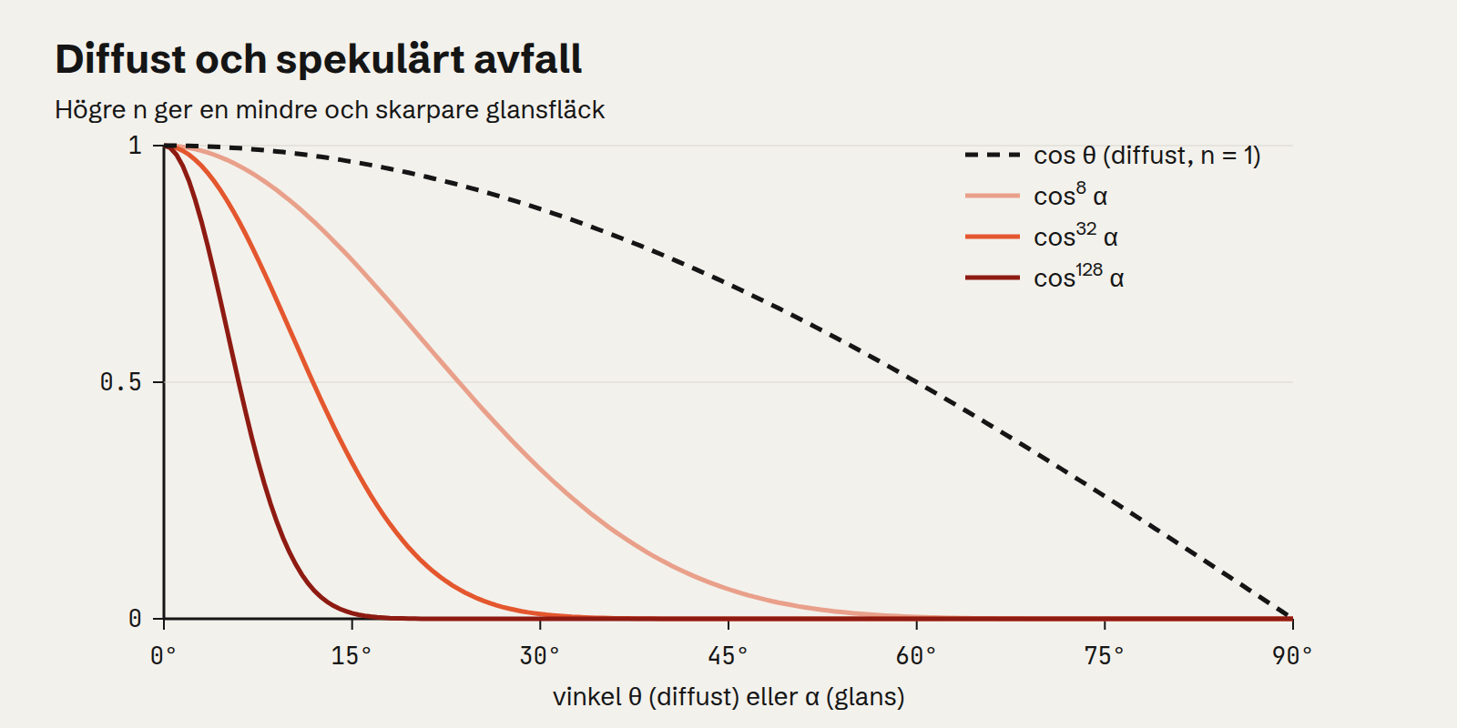
With n = 32, today's default, the highlight is 0.61 of its maximum at α = 10° and 0.14 at 20°.
The light's direction
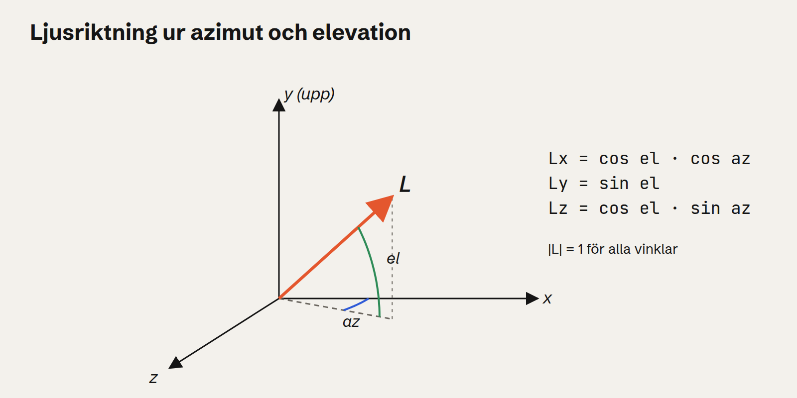
The original took the light's direction as a vector (default (1, 1, 5)) in eye coordinates, so the light followed the camera. Today's version gives it as two angles, azimuth around the vertical axis and elevation above the horizon, and the light stays put in the world when you turn the model:
L = (cos el · cos az, sin el, cos el · sin az)The vector always has length one, since cos² el · (cos² az + sin² az) + sin² el = 1.
A worked example with today's defaults
The defaults in 3D Lab are the colour #b3b3b3, ka = 0.25, kd = 0.75, ks = 0.5, n = 32, ia = 0.51, il = 0.8, ils = 0.5 (the highlight light's intensity), az = 45° and el = 60°. Take a surface pointing straight up, N = (0, 1, 0).
L     = (cos 60° · cos 45°, sin 60°, cos 60° · sin 45°)
      = (0.354, 0.866, 0.354)
N · L = 0.866

ambient = ka · ia       = 0.25 · 0.51        = 0.128
diffuse = kd · il · N·L = 0.75 · 0.8 · 0.866 = 0.520
The colour first has to be made linear. #b3 is 179 / 255 = 0.702 in sRGB, but sRGB is a curve that keeps more steps in the dark. Light adds up in linear values:
linear = ((0.702 + 0.055) / 1.055)^2.4 = 0.451

colour = 0.451 · (0.128 + 0.520) = 0.292       (linear)
sRGB   = 1.055 · 0.292^(1/2.4) − 0.055 = 0.576  →  147 of 255
Without a highlight the surface is #939393. The highlight is added in the light's colour, white:
R         = 2 · 0.866 · (0, 1, 0) − L = (−0.354, 0.866, −0.354)
highlight = ils · ks · (R · V)^32 = 0.25 · cos³² α

α = 0°   →  0.250  →  194 of 255
α = 10°  →  0.153  →  178
α = 20°  →  0.034  →  155
α = 30°  →  0.003  →  148
In the middle of the highlight the surface is #c2c2c2. Thirty degrees away you can hardly see it.
Flat shading
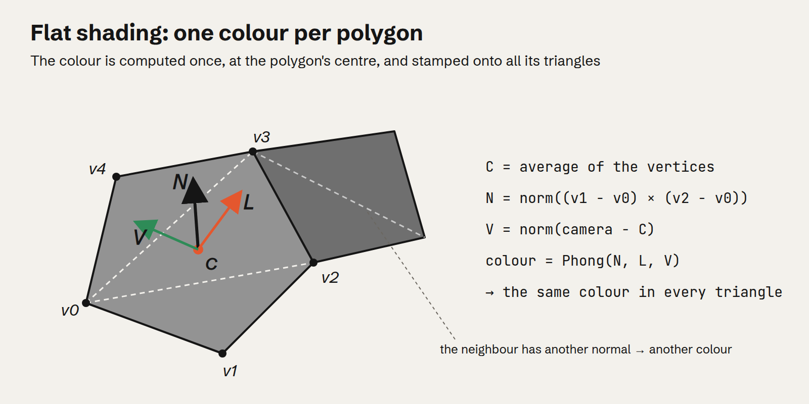
Flat shading was the main task of the lab: every polygon gets a single colour, computed with the polygon's own normal. The edges between faces show, and the model looks the way it is built – out of flat pieces. That also makes flat shading a good test of everything that comes before it: a polygon with the wrong vertex order gets a normal pointing inwards and disappears with culling, or turns dark without it, and you see it at once.
How a polygon's colour is computed
Today's code, the function bakeFlatColors, goes through the polygons in the file – not the triangles. For a polygon with the vertices v0, v1 … vk−1 it computes four vectors:
C = (v0 + v1 + … + vk−1) / k          the centre
N = norm((v1 − v0) × (v2 − v0))       the normal
V = norm(camera − C)                  direction to the eye
L = (cos el · cos az,  sin el,  cos el · sin az)
norm divides a vector by its length. The vertices are first transformed by the model's rotation, so N and C follow when you turn the model, while L stays put in the world.
Then comes Phong's lighting model. The two cosines must not go negative, because a face turning away from the light should not get darker than the ambient light makes it:
d = max(N · L, 0)                     diffuse
R = 2 d N − L                         L mirrored in N
s = max(R · V, 0)ⁿ                    highlight

colour = min( obj · (ka·ia + kd·il·d) + light · ils·ks·s , 1 )
The formula applies to each channel separately, red, green and blue. obj is the material's colour and light the light's, both linear. Notice that the highlight takes the light's colour, not the material's: a white lamp gives a white highlight even on a red surface. min(…, 1) clamps the channel, so a strong highlight turns white instead of wrapping around.
The colour is then written to all the triangles the polygon was split into. Every triangle knows which polygon it comes from (triToPoly), so a pentagon becomes three triangles with exactly the same colour, and the seams between them don't show. To make that possible, the flat-shaded model has its own copy of the geometry where the triangles share no vertices. If two polygons shared a vertex, the vertex could only have one colour, and the GPU would blend the colours across the face.
Why one colour is enough
It is not just a simplification. In a flat polygon N is the same everywhere. The light is directional, like a distant sun, so L is the same everywhere too. Then the ambient and diffuse light – ka·ia + kd·il·(N · L) – is exactly equal at every point on the face, and one colour per polygon is the correct answer.
The only thing that changes across the face is V, and with it the highlight. Flat shading computes the highlight at the centre and uses it for the whole polygon. On a large face a highlight can therefore switch on and off all at once as you turn the model, instead of sliding across the face.
Where the colour jumps
Between two polygons N changes direction, and the colour jumps. Take a cube that isn't rotated, with today's defaults:
face      N            N · L    linear    sRGB
top       (0, 1, 0)    0.866    0.292     147  #939393
right     (1, 0, 0)    0.354    0.153     109  #6d6d6d
front     (0, 0, 1)    0.354    0.153     109  #6d6d6d
left      (−1, 0, 0)   0        0.058      68  #444444
bottom    (0, −1, 0)   0        0.058      68  #444444
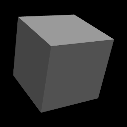
The top is the worked example above. The right and front faces come out equally bright, because the 45° azimuth puts the light exactly between them. The left face and the bottom get only the ambient light, 0.128 · 0.451 = 0.058. The highlight is left out of the table, since it depends on where the camera is.
Every frame
The colours are recomputed every frame, before rendering. It is one calculation per polygon on the CPU – just over 2,000 for the largest model, hazard – and that is plenty fast. That is why the shading follows at once when you drag the model, change the light or move the camera.
1998
The original worked the same way, but in eye coordinates. The normal was (v1 − v2) × (v3 − v2), the centre the average of the first three or four vertices, and since the eye was at the origin, V = −C. The light's direction was also given in eye coordinates, so the light followed the camera. Get_Shade computed three values between 0 and 1, they were scaled to 0–255, and IRIS GL filled the polygon with that colour. The polygons never had to be split into triangles.
The bugs I found in the 1998 code
When Claude Code read the original for this post it found three bugs in the lighting function Get_Shade, and a weakness in how the colour is rounded:
- R · V is computed wrong. The line is
rx*vx + rx*vx + rx*vx– the x component three times, instead ofrx*vx + ry*vy + rz*vz. So the highlight depends only on the x direction of the reflection. - Only red light. The direct light is multiplied by
il[1], the red component, in all three channels. Il's green and blue values do nothing. - The reflection is computed with unnormalised vectors. Cos θ is correctly divided by the lengths, but R = 2 (N · L) N − L is computed with N and L as they are. The normal is a cross product of edges, and its length grows with the size of the face.
- Colours of 1 or more are not written. A channel is scaled to 0–255 only if the value is below 1. Otherwise it keeps the previous polygon's value.
It doesn't show much in the screenshots – most of the light is diffuse, and that was computed correctly. Today's flat mode computes the same model without the bugs: with normalised vectors, all three components, max(0, …) on both cosines and the colour clamped to 1.
The same lab in three.js
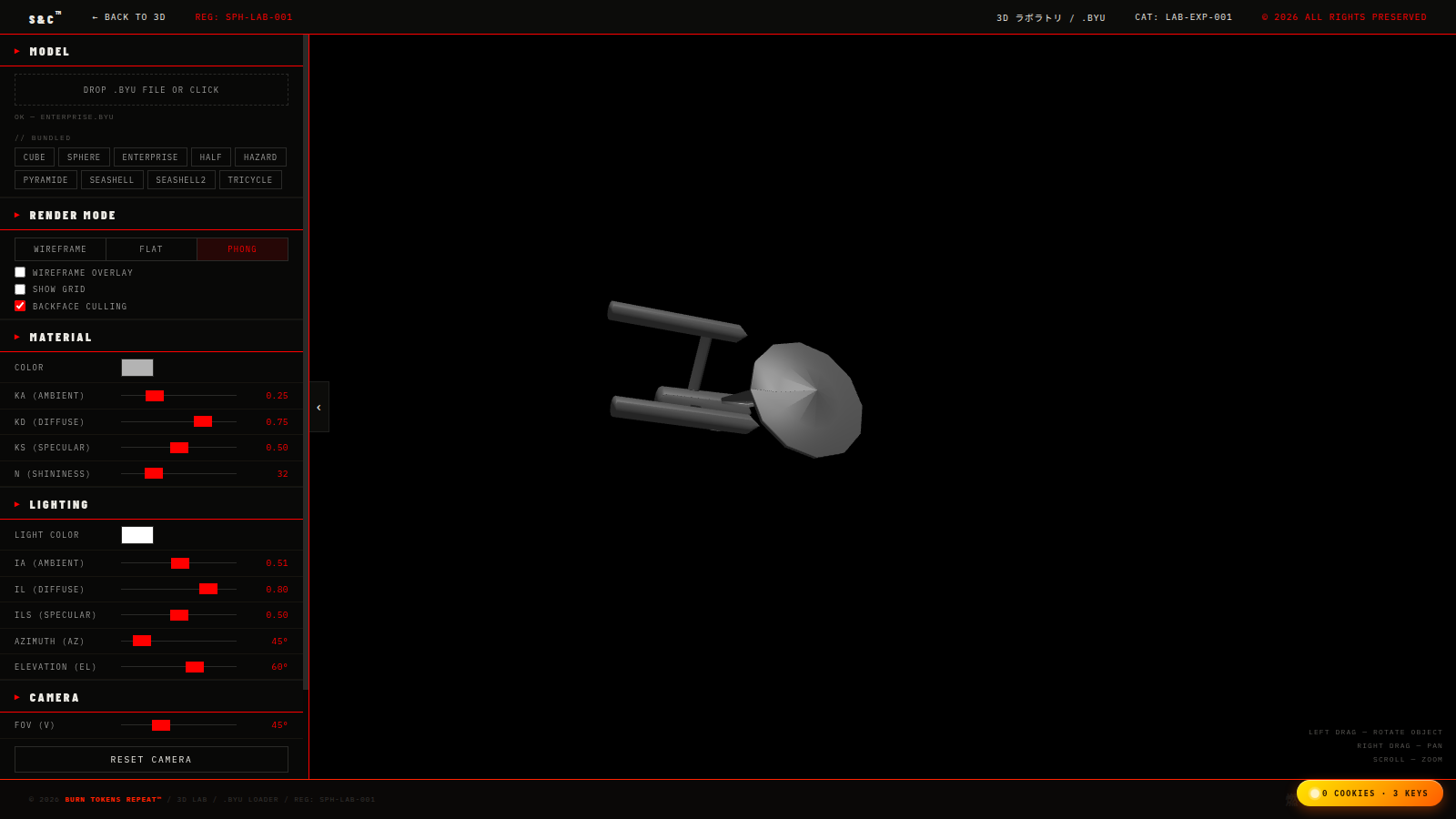
Claude Code translated the lab into a single page with three.js. This is what differs from the original:
- The camera. Instead of entering F, A and U you drag the model. A drag becomes a rotation around an axis perpendicular to the drag, with the angle proportional to the drag's length. The right button pans and the wheel zooms.
- The model is normalised. Every model is moved so that the centre of its bounding sphere is at the origin and scaled to radius 1. That way every model fits the view from the start.
- A z-buffer instead of sorting. The GPU decides per pixel what is closest.
- Triangles. The polygons are split into fans, but the wireframe draws only the original edges.
- The light stays put in the world and is given by azimuth and elevation.
- Linear colours. The light is computed on linear values and converted to sRGB on the way out. The original computed directly on the values.
Nine models are included: cube, sphere, enterprise, half, hazard, pyramide, seashell, seashell2 and tricycle. Five of them come from the course: cube, enterprise, half, hazard and pyramide. The sphere and the two seashells were generated afterwards with small scripts, and the tricycle is a simpler stand-in – the more detailed one in the 1998 screenshot no longer exists. You can also drop your own .byu file on the page.
The same thing with three.js's own functions
Today's 3D Lab still computes some things itself – the colour of each polygon and the culling of the wireframe – to show the maths. Let three.js do everything it can, and the same thing takes just over 50 lines. The only thing missing is the format: three.js has no reader for Movie.BYU, so you write that yourself.
import * as THREE from "three";
import { OrbitControls } from
  "three/addons/controls/OrbitControls.js";

// Movie.BYU: header, part ranges, x y z per vertex,
// then 1-based indices; a negative index ends a polygon.
function parseBYU(text) {
  const t = text.trim().split(/\s+/).map(Number);
  const [parts, nv, , nc] = t;
  let i = 4 + 2 * parts;
  const pos = t.slice(i, (i += 3 * nv));
  const idx = [];
  let poly = [];
  for (const v of t.slice(i, i + nc)) {
    poly.push(Math.abs(v) - 1);
    if (v > 0) continue;
    for (let k = 1; k < poly.length - 1; k++)
      idx.push(poly[0], poly[k], poly[k + 1]);
    poly = [];
  }
  const g = new THREE.BufferGeometry();
  g.setAttribute("position",
    new THREE.Float32BufferAttribute(pos, 3));
  g.setIndex(idx);
  return g;
}

const scene = new THREE.Scene();
const camera = new THREE.PerspectiveCamera(
  45, innerWidth / innerHeight, 0.01, 100);
camera.position.set(0, 0, 3);

const renderer = new THREE.WebGLRenderer();
renderer.setSize(innerWidth, innerHeight);
document.body.append(renderer.domElement);
new OrbitControls(camera, renderer.domElement);

scene.add(new THREE.AmbientLight(0xffffff, 0.5));
const sun = new THREE.DirectionalLight(0xffffff, 2);
sun.position.set(1, 2, 1);
scene.add(sun);

const res = await fetch("hazard.byu");
const geo = parseBYU(await res.text());
geo.center();
geo.computeBoundingSphere();
const s = 1 / geo.boundingSphere.radius;
geo.scale(s, s, s);

scene.add(new THREE.Mesh(geo,
  new THREE.MeshPhongMaterial({
    color: 0xb3b3b3, flatShading: true })));

renderer.setAnimationLoop(() =>
  renderer.render(scene, camera));
The code assumes that three and three/addons/ point to three.js, for example with an import map, and that hazard.byu sits next to the page.
This is what three.js takes care of, of what the lab computed by hand:
- The camera and the perspective.
PerspectiveCamerabuilds the projection from the view angle, 45°, andOrbitControlsmoves the camera with the mouse. No F, A, U or T = 2 · tan(v / 2). - The clipping. The GPU clips against the six sides of the view volume. No Cohen–Sutherland.
- Backface culling. The material's
sideisTHREE.FrontSidefrom the start, so the back faces are not drawn. - Visibility. The z-buffer is on from the start. No sorting.
- The normal. With
flatShading: truethe face's normal is worked out in each pixel from the screen coordinates, so no normals need computing beforehand. - The light.
MeshPhongMaterialwithAmbientLightandDirectionalLightgives ambient light, diffuse light and highlights – the highlights Blinn's way, with the half vector. - The colours. three.js computes on linear values and converts to sRGB on the way out.
- The size.
center()and the bounding sphere replace the normalisation.
For a wireframe without the triangles' diagonals, new THREE.EdgesGeometry(geo) is enough: it keeps only edges where the faces meet at an angle.
The result is almost the same as 3D Lab's flat mode, but not quite. The normal is the same across the whole polygon, so with directional light the ambient and diffuse light come out the same – just as in the section on why one colour is enough. But the light is computed in every pixel, so a highlight can slide across a large face instead of applying to the whole polygon. And a polygon that isn't quite flat can get different shades in its triangles, where 3D Lab gives the whole polygon one colour.
Try it yourself
3D Lab is at burntokensrepeat.com/3d/lab. Pick a model, switch between wireframe and flat, turn culling off and watch the back faces appear, or raise n and watch the highlight shrink. The links to the sources on Movie.BYU are next to the post.